Deconstructing Melvin:
Some time has passed since we have posted anything, so we are going to try to write something somehow interesting. This post is versed about the making of the one sweet project developed in our studio, it is called #translatingmelvin.
Project:
On December of 2011 we received one call from Ruben Martínez of Hommu Studio, he wanted to talk to us about one crazy and funny idea that we loved the first minute we heard about it…
The idea consisted about translating the language of the plants.
The project consists of a webcam transmitting the image of a plant in real time, this plant had to mount some control sensors (humidity, temperature, lighting), and with the values obtained from them we had to define the mood of a plant called Melvin. The development also required an artificial intelligent that allowed the user maintain one conversation with Melvin, and the answer would be different depending on the mood of the plant.
Talking with Ruben we realized that there was no interactivity with the installation, so we gave him some ideas like activating one air pump that could create bubbles in a water container, or dropping soap bubbles, or maybe turning on or off one light, perhaps watering the plant, or opening a curtain close to the plant. Something that could help the user to feel that the installation really existed and he/she could interact with it. Sadly no one came to prosper.
Melvin also had to emit via Twitter the generated answers in the conversations with every user. We also had to develop a system in order to talk with Melvin from Twitter using the hashtag #translatingmelvin. With this we had the social part of the project covered.
Production
Instalation
We had been working some time with one data acquisition hardware from National Instruments, using LabView and some sockets connections to perform hardware control of the things we could do in Flash. Even though, for this project, we decided to give a try to Arduino and Operframeworks.
From this blog we would like to congratulate and send our admiration to the teams of both projects, Arduino and Openframeworks are very powerful solutions and very well documented, with a quite big community of people giving solutions to issues more or less difficult. And the best part of all is that all this information is given in an altruistic way, and it is available to anyone who has a little interest in learning about these projects.
The components
The first step was to choose the electronic components that we should use. We found a big help from an internet store called Farnell.com, thay have very good prices, and almost any component that you need. The delivery is also very fast; we had what we needed the next day before 12h. This last paragraph sounds like a paid comment inside one post, but when you try to find a humidity sensor in your local electronic store you feel relief that Farnell exists.
We knew that we were going to connect the components to an Arduino, at the beginning we were going to use an Arduino UNO, but finally we decided to connect everything to an Arduino Mega since we needed more analog outputs to move seven relays.
To sense the humidity we used one sensor called “Sensirion SHT11”, this is a digital sensor that presents some issues since we had to use one cable larger than 5cm, and the signal was lost in the way. We had to use one capacitor and isolated cable as is explained in the datasheet of the sensor. The capacitor makes the signal stable along the way, and it allows us to read it with a sufficient intensity to be read without losing any bit in the journey.
To obtain the light intensity we used a Vishay Siliconix BPV22NF photodiode, this is an analog sensor and it was as easy as to send some current intensity to the enter pin and read the current intensity of the output pin.
For the temperature we used a LM35 sensor, this analog unit works in a similar manner that the photodiode, you feed it with current and you obtain a variable output that defines the actual temperature.
Circuits
To turn on the light bulbs that represent the mood of the plant we had to commute the 220V alternate current using the 5V direct current from Arduino, so we also needed a set of solid state relays. These are the Sharp PR39MF51NSZF, following the instructions from the datasheet we had everything mounted in a couple of minutes.
After we had the commuting system for the 220V bulbs, we started to make some tests in the plant´s installation and we found that the image from the webcam got burned when the light´s conditions were even low or light low, so we had to create a system that allowed us to dimmer the light depending on the current lighting from the surroundings. The bad news was that it was not possible with the actual components that we had selected.
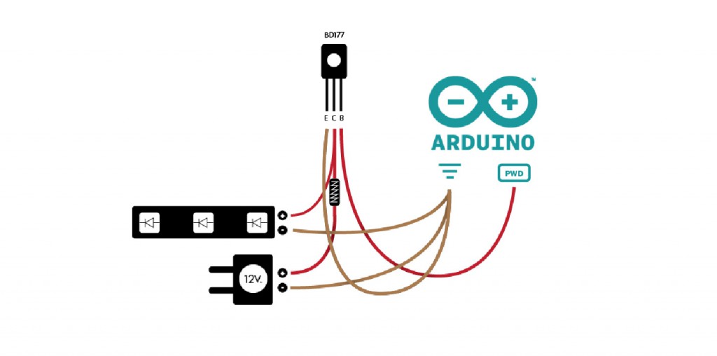
We had to change the actual bulbs because these bulbs do not allow us to dim the light intensity, so we adopted a solution of 3 leds bulbs that we could dimmer using transistors as current amplificator, the leds work with 12V DC hence we don´t needed the relays anymore. The basic circuit is shown in the next image.
The previous circuit is controlled using the values obtained from the photodiode, as the lighting from the room increases, the lighting from the leds increased too and vice versa. This way we found that the image from the webcam was never burned and people could read the icons from the mood in low lights conditions.
Software
In order to control the whole hardware we wrote one application in C++ using the Openframeworks libraries.
In the first place we have mounted a connection system with Arduino to control the sensors, to make it we used the “OfArduino” class, this requires that Arduino gets provided with the sketch of “Firmdata Standard”. Once the “Firmdata” was installed, we could setup and manage the pins from the board directly from the C++ code running in the computer.
This way we could send and read the volt from the pins of the sensors, or we could send volt to any given relay to turn on or off the 220v bulbs, or modulate the current applied to the transistors for the Leds dimming.
The application logic is quite simple. It is just a state machine.
One of the issues we had to deal with was that the sensor SHT1x (the one for the humidity and temperature) has a protocol that requires to send pulses with a nanoseconds frequency. Using Firmdata to communicate with this sensor is not adequate.
The solution for this problem was to move the communication code into the Arduino Board, since we can send high frequency pulses from the board to a specific pin. Finally we had to merge the Firmada Standard code with the communication code for the sensor.
Once we obtained the humidity and temperature values from Arduino, we had to send those values back to Openframewors, this was made hacking the code from Firmdata. We defined to virtual pins of Firmdata to be the ones that send the values obtained from the sensor, we also had to insert one exception in the read and write pins buckle of Firmdata so it would not read or write anything from those pins.
Then we could send the values obtained from the sensor to those pins.
currentMillis = millis();
if(currentMillis - previousMillis > samplingInterval) {
 previousMillis += samplingInterval;
 for(pin=0; pin<TOTAL_PINS; pin++) {
 if(IS_PIN_ANALOG(pin) && pinConfig[pin] == ANALOG) {
 if(analogInputsReport & (1<<analogPin)) {
 if(analogPin != HUMIDITY_PIN)
 if(analogPin != TEMPERATURE_PIN) Firmata.sendAnalog(analogPin, analogRead(analogPin));
 }
 }
 }
}

Firmata.sendAnalog(HUMIDITY_PIN, humidity);
Firmata.sendAnalog(TEMPERATURE_PIN, temp_c);
In the Openframework´s code the value arrived without any issues, like it were to more regular pins.
The communication between the Flash application and Openframeworks was made with a Sockets server using the addOn ofxNetwork, specially the ofxTCPServer class.
The politics of Flash about crossdomains require that if you want to establish a net connection via Sockets with the navigator, the socket server must send, by a specific port, on string containing a Crossdomain.xml giving access as many domains as the user wish. This was made leaving the 2048 port opened and dedicated for this only task. When someone established one connection through the sockets to this port, this function was called:
void myApp::returnXMLPolicy(int id){
string policy = “<?xml version=’1.0′?><!DOCTYPE cross-domain-policy SYSTEM ‘/xml/dtds/cross-domain-policy.dtd’><cross-domain-policy><site-control permitted-cross-domain-policies=’master-only’/><allow-access-from domain=’mydomain.com’ to-ports=’*’ /></cross-domain-policy>\n”
socketPolicy.send(id, policy);
}
And it worked succesfully
Once the exchange of files was made, the connections between the designed port and the client could be initiated, that allowed us to obtain persistent connection in real time with a web browser. It is very easy to implement and it is very stable. We made proof with more than 100 connections at the same time and the application worked just time.


