In the last post we talked about the implementation of volume shadows in a particle system, this last approach used a couple of for loops in order to define the final shadow intensity for each particle. This loops could make that the application has to evaluate 32 * nParticles the shadow map, making the process somehow very low.
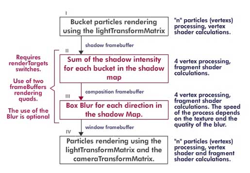
So we tried a pair of optimizations that would deal with the defects of the previous work, the first thing we have done is to change all the texture reading to the fragment shader, and then we tried to make the sum of the shadows for each step with the fragment shader also. At the end of the working process we defined the next steps to get the shadows done.

First Step: Shadow Buckets
The first step is no different that the last approach, we defined 64 buckets in the vertex shader using the depth of the particles assuming that all of them are inside a bounding box, then we render them in a shadow framebuffer defining a color depending on the shadowDarkness variable. For this step we use the same getDepthSlice function in the vertex Shader.
void getDepthSlice(float offset, mat4 transformMatrix) {
vec3 vertexPosition = mix(aVertexFinalPosition, aVertexPosition, uMorpher);
eyeVector = vec4(vertexPosition, 1.0);
eyeVector = transformMatrix * eyeVector;
gl_Position = uPMatrix * eyeVector;
desface.w = 64.0 * (gl_Position.z – uShadowRatio + uBoundingRadio) / (2.0 * uBoundingRadio) + offset;
desface.z = floor(desface.w);
desface.x = mod(desface.z, 8.0);
desface.y = floor(desface.z / 8.0);
desface.y = 8.0 – desface.y;
gl_Position.x -= gl_Position.w;
gl_Position.x += gl_Position.w / 8.0;
gl_Position.x += 2.0 * gl_Position.w * desface.x / 8.0;
gl_Position.y += gl_Position.w;
gl_Position.y -= gl_Position.w / 8.0;
gl_Position.y -= 2.0 * gl_Position.w * desface.y / 8.0;
}
There is one very important difference in this function from the previous one, this new one requires two parameters, one offset and the transformMatrix. The second one is used to tell the function which view (camera view or light view) is used to define the buckets, this is usefull If you try to use the buckets system to sort the particles and blend the buckets.
The first parameters offers you the possibility to obtain the next or previous bucket from a given depth, with this we can interpolate from two buckets or layers, that would give us a linear gradient of shadows between two layers instead of 64 fixed steps.
Second Step: Shadow blending
This step is the main optimization from this code, what it does is to blend the previous bucket into the next so you can define all the shadows for each layer in 64 steps. Blending the buckets require to use the gl.BLEND and to define the gl.blendFunc using gl.ONE and gl.ONE.
Then you have to render one quad to the shadow framebuffer using the shadow map of the shadow framebuffer as a texture, the most important thing here is to get the bucket coordinates for each of the 64 passes for the quad. This is also done in the vertex shader, with each pass, one depth is defined for the quad and the vertex shader defines the UV texture coordinates using the next chunk of code
if(uShadowPass == 2.0) {
desface.x = mod(uDepth, 8.0);
desface.y = floor((uDepth) / 8.0);
gl_Position = vec4(aVertexPosition, 1.0);
gl_Position.xy += vec2(1.0, 1.0);
gl_Position.xy /= 2.0;
gl_Position.xy = (gl_Position.xy + desface.xy) / 4.0;
gl_Position.xy -= vec2(1.0, 1.0);
desface.x = mod((uDepth – 1.0), 8.0);
desface.y = floor((uDepth – 1.0) / 8.0);
vTextureUV.xy = (desface.xy + aVertexUV.xy) / 8.0;
}
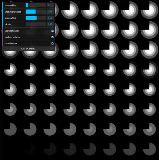
There is no big deal here, what it does is to define the coordinates depending on the depth written as X,Y values (depth = 8 * y + x), as you can read we define one vec2 call “desface” that holds the X,Y values used for the texture. The next image shows the result of this blending

Third Step: Blur passes
This step has no difficulty, but requires the use of a composition framebuffer for a intermediate destination, this is made to avoid the forward loops in one texture. We defined the blur in two differents passes, one for the X component and another for the Y component, we used a simple box blur but you can perform a gausian blur or some other blur you like.
Fourth Step: Particles rendering
In this final step we render all the particles to the window framebuffer using the shadow texture, the lightTransformMatrix and the cameraTransformMatrix, first we transform then to the light view to read the correct shadow intensity from the map.
In this part of the process you could read the shadow force for the particle depending on the depth and the bucket, but this would make that all the particles in the same bucket would show the same “force” even though their initial depth are different. This is when we use the offset parameter from the getDepthSlice function, for a given depth and bucket we can obtain the current bucket and the next one and interpolate the shadow force of the current depth between those two layer.
Once the shadow force is defined we have to transform the particle position to the camera view to obtain the light attenuation and position of the particle, and finally render it.
In the vertex shader we have this chuck of code:
if(uShadowPass == 3.0) {
getDepthSlice(1.0, uLightTransformMatrix);
vTextureUVNext = vec2((gl_Position.x / gl_Position.w + 1.0) / 2.0, (gl_Position.y / gl_Position.w + 1.0) / 2.0);
vInterpolator = desface.z – desface.w;
getDepthSlice(0.0, uLightTransformMatrix);
vTextureUV = vec2((gl_Position.x / gl_Position.w + 1.0) / 2.0, (gl_Position.y / gl_Position.w + 1.0) / 2.0);
vec3 vertexPosition = mix(aVertexFinalPosition, aVertexPosition, uMorpher);
eyeVector = vec4(vertexPosition, 1.0);
vec4 lightVector = vec4(uLightVector, 1.0);
float distance = abs(dot(lightVector.xyz , eyeVector.xyz) – dot(lightVector.xyz , lightVector.xyz)) / length(lightVector.xyz);
vAttenuation = distance * distance;
vAttenuation = vAttenuation < 1.0 ? 1.0 : vAttenuation;
eyeVector = uCameraTransformMatrix * eyeVector;
gl_Position = uPMatrix * eyeVector;
}
Here we get the uvTexture coordinates for the current bucket and the next one (notice that we call the getDepthSlice function using an offset of 0.0 and 1,0), there is also the attenuation calculation in for each particle in this shader.
In the fragment shader the code goes like this:
if(uShadowPass == 3.0) {
vec4 color1 = vec4(0.7, 0.3, 0.2, 0.05);
vec4 color2 = vec4(0.9, 0.8, 0.2, 1.0);
gl_FragColor = mix(color2, color1, uMorpher);
float shadow;
if(uUseInterpolation) {
float shadowForce = texture2D(uSampler, vec2(vTextureUV.x, vTextureUV.y)).r;
float shadowForceNext = texture2D(uSampler, vec2(vTextureUVNext.x, vTextureUVNext.y)).r;
shadow = mix(shadowForceNext, shadowForce, vInterpolator);
} else {
shadow = texture2D(uSampler, vec2(vTextureUV.x, vTextureUV.y)).r;
}
gl_FragColor.rgb *= (1.0 – shadow);
if(uUseAttenuation) gl_FragColor.rgb = 1.0 * gl_FragColor.rgb / vAttenuation;
gl_FragColor += ambientColor;
}
Here we can define a color tint for the shadow, we also read here the shadow from the texture in the current bucket and the next one to perform the interpolation fot the final shadow intensity.
And that is it, four steps to render the shadows, this steps gives you the chance to blur the shadows, make some interpolations between two shadow layers and the possibility to tint the shadows. But it has some disadvantages too, this process requires multiple changes of render targets, and it requires a good variables definition to make it work.
In the example (click on the first image if you haven´t done it yet) you can see these variables to play with:
– shadowBlur: it defines the blur in the shadow map.
– shadowDarkness: as it name says, it makes the shadow darkness or lighter inside the volume and the shadow applied in the floor.
– shadowTint: it “tints” the shadow with the particles color.
– lightAngle: it allows you to change the light direction from 0 to 45 degrees, this helps you to see how the shadows change in the volume and on the floor depending on the position of the directional light (remember that it´s always pointing to the center of the object).
– cameraRatio: this ratio gets you closer or farther to the volume.
– useAttenuation: it toggles the light attenuation over the distante (squared), if on you will see the effects of the shadows plus the attenuation, if off you will see only the shadows in the volume.
– useInterpolation: it toggles the interpolation between two buckets for a givven depth of a particle in those two layers. With a high bRatio and this variable off you should see the segmentations of the shadow in the volume.
– showTexture: it shows you the final shadow map used for the volume shadows and the floor shadow. To read it right you should start from botton to the top. The closest points to the light are in the left down corner of the image, and the final shadow (the one used in the floor) is in the top right corner of the imagen.
– bRatio: this is the most important variable of the whole process, this float defines the bounding sphere ratio that contains the volume. You must define one sphere that holds all the particles inside or you will find some glitches in your rendering. But beware, you could be tempted to define a big bounding sphere for the current volume, but what you are really doing is assigning less layers for the volume.
For this example is really ease to define the bRatio, but when you are animating the lights and the particles things starts to get messy and the only thing left is to define a big bounding sphere. If this is the case you could end up with 16 to 8 layers for one volume, and that is when the interpolation of the buckets information helps. Try to play around with this variable and turn on and off the interpolation and you will see the effects of it.
As we said before we hope we could write a third article using this method to do some animations.
