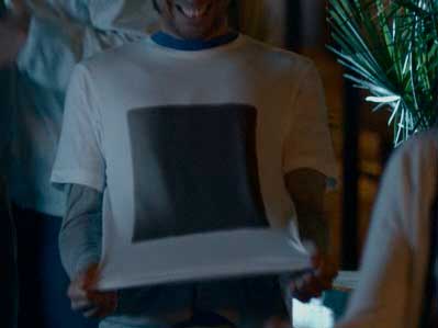
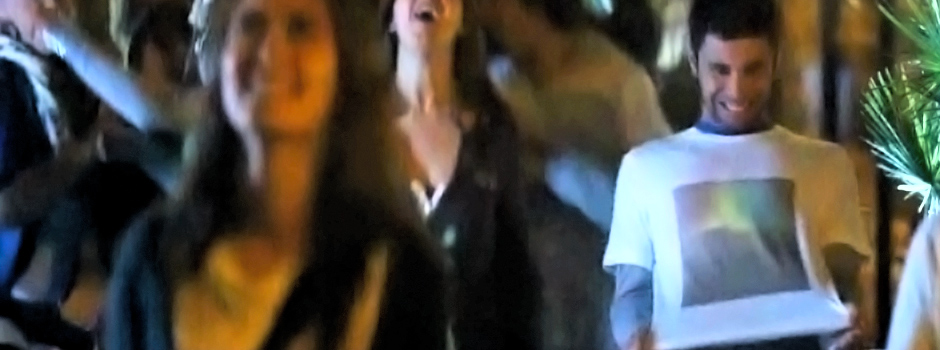
Many sites have been done implementing the interaction between video and photos, text, or any other additional assets that could be inserted in the original video to enhance the final experience. Tracking simple planes can be done very easy with the help of After-Effects or any other post- production software, but when it comes to track complex surfaces there is not a simple way to do it.
We were asked to develop one way to track surfaces for one project designed by David Navarro (www.davidnavarro.net). David wanted to track one t-shirt in order to place the users photo in the chest of the t-shirt. So after thinking how we could make it we got the main idea in five simple steps:
1. Track predefined control points placed in the t-shirt with the help of After-Effects.
2. Modify the video in order to create the mask and the shadings that would affect the mesh previously created.
3. Define one Nurbs-Mesh using the tracked control points in the t-shirt.
4. Create a color correction for the inserted image by the user.
5. Integrate the mesh and the video for the final result.
Tracking Control Points:
When it comes to track control points in a t-shirt the first idea that came to us was to draw a grid of points in a t-shirt, and try to track them with Motion. The main problem with it is that if you define an 8×8 grid you would end up tracking 64 for points per frame, (that would probably not be well tracked so you would be editing many frames in order to get the result that would be required).
So instead of tracking points we ended up tracking regions, these regions are defined as four corners areas that would be equidistantly defined in the original grid of points (see next image).

In the image below there is a rectangular region of the chest that would be changed with one image defined by the user. This region contains rectangular areas that would be tracked using Mocha (a plug-in for After Effects). Since all the squares share at least one corner with each other, only the black squares in the t-shirt must be tracked in order to get all the control points needed.
Once the squares are tracked for all the needed frames, you should re-order the four corners obtained for each square in order to rewrite the points in a row-column ordered format used to create one interpolated Nurbs Mesh. Finally you could export these points with the X, Y and Frame information in a XML to use in Action Script.
Video Masking and Shading:
Since we are not specialist in video post-production, we counted with the help of Manolo Calvo (www.freelancetv.es), he was responsible of the final tracking of the rectangular regions, but most important He was the guy that made the masking and shading of the video in order to superimpose lights and shadows to the generated mesh. Video masking can be done using the mesh generated with the original control points, one thing to take into account is that this mask should be smaller than the final integrated mesh in order to avoid holes between the mesh and the video.
In this work this was not the case, Manolo made the masking by hand, and he also painted the lights and shadows over the video in order to give us a final composition with the alpha channel ready to integrate the final mesh. In the next image you can see the final result of the video composition with the lights and shadows added.

Creating the Nurbs Mesh:
Using the Classes commented in these previous posts (http://labs.miaumiau.cat/?p=178, http://labs.miaumiau.cat/?p=338), we could interpolate one mesh with the original control points, the final mesh could have the resolution needed to show the final image in a flexible way, and it also allowed us to modify the behavior of the interpolation (the degree of the final mesh in the u,v directions). Depending of the typology of the surface you could decide the way you could interpolate the surface, if the internal points do not affect the final interpolation, you could interpolate using only the border curves of the surface, in the other hand if the surface has big changes in its interior you should interpolate using all the control points defined in the grid of the t-shirt (or the surface you are tracking in the video).
Color Correction:
The final video made by Manolo had desaturated colors, low values of contrast and also low values of brightness, so in order to adapt the final mesh to the video some color corrections should be done to the image inserted by the user. In order to do so we programmed a set of modifiers for a given bitmap data and we tried with many pictures in order to define the final values of contrast, brightness, saturation and blur that would by applied to each image inserted. Every time one image is going to be inserted in the t-shirt the values of these parameters are changed to make the final color correction.
Using this correction and the shading created over the video would give the illusion of integration between the mesh and the video.
Video and Mesh Integration:
Having the video post-produced with the alpha channel and the lights and shadows painted in the final composition, integrating the mesh for the final result is very easy. The mesh must one layer under the video so this last one can affect the mesh representation like a multiply blend mode.
So using the five previous commented steps, we have programmed one simple example (click on the first image) that shows the final integration in the video. You can change between one image or the webcam, you can also change the depth of the video and the mesh to see how the video affects the mesh, and finally you can see how the mesh is created.
Finally we would like to thanks Manolo & Ivan for their invaluable help with the video tracking and post-production for this project.
